* These are Tibbo BASIC/C-programmable devices and their function depends on the loaded app.
We offer many ready-to-use apps, among them a serial-over-IP (SoI) app and Modbus Gateway app.
PLUS1 Application CPUFeaturesSpecifications

Plus1 (SP7021) Features

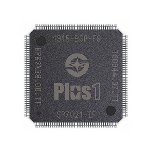
Easy-to-Use LQFP Package

The Plus1 is available in an easy-to-use 20x20mm LQFP176-EP package. Unlike BGAs, TQFP ICs are easily handled by humans; for example, they can be hand-soldered during the assembly of board samples. TQFP packaging also simplifies the PCB layout work and facilitates the use of lower-cost, four-layer or two-layer PCBs. This alone leads to substantial cost savings compared to six and even eight-layer boards often needed to accommodate BGA-packaged CPUs! In their simplicity, your boards will look more like a typical "microcontroller" rather than "typical Linux CPU" designs.

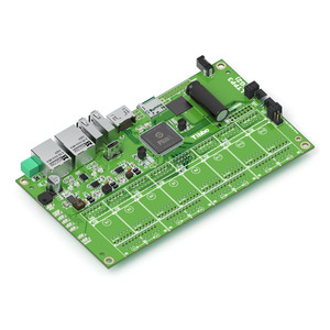
See the difference...

Quad-Core 1GHz Cortex-A7 CPU + A926 and 8051 Cores

The Plus1 boasts a quad-core 1GHz ARM Cortex-A7 (CA7) processing unit plus two additional CPU cores: a 202MHz A926 core for executing real-time code and a low-power 202MHz/32KHz 8051 core for system management (including in low-power standby mode). All GPIO lines and peripherals are accessible from all cores of the chip.

Single 3.3V Power

While many of its competitors require up to three different supply voltages, as well as complex and costly power management ICs, the Plus1 can run off a single 3.3V power source. All additionally required voltages — 1.8V, 1.2V, and 0.9V — are generated internally*. Only a few passive components are needed to complete the power circuits.

* Some limitations apply to the use of the internal 1.2V power regulator.

Integrated 128MB or 512MB DDR3 DRAM

The Plus1 incorporates 128MB or 512MB of DDR3 DRAM. This dramatically simplifies the PCB layout — no more copying and pasting known-good DRAM traces from proven PCBs, worrying about trace impedances, or going through costly and time-consuming layout iterations. The DRAM is built-in, and it just works! Integrated DRAM also means that you will be able to reduce the number of board layers to four or even two. Finally, by putting the DRAM into the Plus1, we've made your sourcing work easier: DRAM prices and lead times are famously volatile, so the right parts are often hard to procure — with the Plus1, you have one less part to worry about!

Eight 8-bit 5V-Tolerant I/O Ports + One High-Current Port

The Plus1 has eight 8-bit I/O ports with 3.3V logic levels and 5V tolerance. This simplifies interfacing with real-life hardware and eliminates the need for level shifters and other glue circuitry. 5V tolerance is unheard-of on Linux processors, which usually cannot go over 3.3V and often have even less-convenient 1.8V or 1.2V-level I/O.

The Plus1 also has one more 8-bit I/O port, which has a higher driving current ability and hosts a console UART.

Flexible Peripheral Multiplexing (PinMux)

The I/O functions of many of the Plus1's peripherals are routed via a fully symmetrical multiplexor known as PinMux. PinMux allows you to connect any I/O line of any participating peripheral to any of the 64 GPIO lines of eight 8-bit I/O ports.

Many Linux processors have PinMux functions, but they are usually minimal and only provide two or three alternative "routings" for each peripheral. The choices available for one peripheral often conflict with the options offered for other peripherals. As a result, developers are forced to play a complex optimization game that leads to uncomfortable sacrifices and convoluted pin mappings. There is no such pain on the Plus1 — any I/O line of any participating peripheral can be connected to any PinMux pin! What's more, PinMux mappings can be altered on the fly and without rebooting Linux.

Dual PinMuxable Ethernet MACs

The Plus1 incorporates dual PinMuxable 10/100Mb Ethernet MAC controllers and a built-in transparent Ethernet switch. More and more industrial products require dual MACs to daisy-chain Ethernet devices or to connect two independent networks for increased operational reliability. The Plus1 supports both configurations.

In the switch configuration, the OS will detect a single Ethernet adapter. The built-in switch fabric will transparently route external traffic between the two physical Ethernet ports — no processor involvement required. In the dual-port configuration, the OS will detect two independent Ethernet adapters.

All I/O lines of the MAC controller are PinMuxable and can be routed to any of the 64 GPIO pins managed through PinMux.

Four PinMuxable Enhanced UARTs + One Console UART

IoT and industrial control devices always require multiple UARTs, so we paid particular attention to this part of the design. The Plus1 features four identical UARTs with 128-byte TX and RX buffers, automatic RTS/CTS flow control, and baud rates of up to 928Kbits/second.

All I/O lines of all four UARTs are PinMuxable and can be routed to any of the 64 GPIO pins managed by PinMux. There is also an additional console UART with fixed, dedicated TX and RX lines.

Industrial operating temperature range: -40°C to 85°C

The Plus1 is an industrial-grade design through-and-through. The chip supports an operating temperature range of -40°C to 85°C and is well-suited for demanding industrial applications.

Low EMI Simplifies Certification

When designing the Plus1, we paid special attention to lowering EMI. It is no secret that some chips create EMI certification problems, which are notoriously difficult to overcome. This is because many IC vendors consider EMI issues to be board and device-level issues, and do not think that combating EMI is their responsibility. This view is not entirely accurate. A sensible chip design can go a long way toward simplifying subsequent device certifications. We did our homework, and this makes doing yours easier.

Modern, Yocto-based Linux Distribution

Unlike competing chips that often come with outdated Linux distributions (meant only to prove that the IC can run Linux in principle), the Plus1 is supported by a modern, Yocto-based Linux.

Yocto is a widely used framework for managing the pieces that go into a Linux build. According to Wikipedia, the Yocto Project's goal is to "produce tools and processes that enable the creation of Linux distributions for embedded and IoT software that are independent of the underlying architecture of the embedded hardware."

Ten-year Supply Guarantee

The Plus1 was created for industrial applications and devices. We understand that in the industrial space, many products have much longer lives compared to consumer products. Unfortunately, most semiconductor vendors, especially in Asia, primarily target consumer applications and force rapid upgrade cycles of their silicon. To industrial product makers, these rapid upgrades look like "unintelligible flickering" — the pace of change is too fast to even react to it! We understand that, as a designer of IoT and industrial devices, you cannot afford to redesign your product constantly. When you build your product around the Plus1, you choose stability over the "white noise" of other vendors.

And More...

  • Flash interface Supporting eMMC, SPI NAND, and SPI NOR memories
  • PinMuxable SD2.0 interface
  • PinMuxable SDIO (SD2.0) interface (intended for connecting a Wi-Fi/BT module)
  • Two OTG USB2.0 ports with Linux boot and USB video class support
  • Four PinMuxable buffered SPI modules
  • Four PinMuxable buffered I2C modules
  • Two PinMuxable 4-channel PWM modules
  • Four PinMuxable timers/counters
  • Four PinMuxable capture modules
  • MIPI-CSI camera interface for up to two cameras supporting resolutions up to 1328x864 @ 60 fps
  • MIPI video interface supporting resolutions up to 1366x768 and 1312x816
  • HDMI 1.4 video interface for connecting monitors with up to 720p resolution
  • TFT LCD controller with parallel bus interface (resolution up to 320x240x24)
  • I2S/SPDIF/PWM audio output for up to five channels
  • PDM interface for an 8-channel MEMS microphone array
  • 32-bit FPGA bus IO (FBIO) interface
  • Temperature sensor for estimating the internal temperature of the IC
  • Real-time clock (RTC) with an alarm (system power on) function, dedicated backup power input. and backup battery (supercapacitor) charging circuit
  • 128-byte one-time programmable (OTP) memory carrying vendor/device IDs, two registered MAC addresses, as well as providing 64-byte space for user data
  • SWD and JTAG debug interfaces
  • Watchdog timer
  • Secure boot: boot image verified by ED25519 algorithm
  • PKA engine (RSA), hash engine (SHA3, MD5), and encryption/decryption engine (AES)

See Plus1 technical specifications

Order Plus1 Chips Today!

Also available on Digi-Key!

PLUS1 Application CPUFeaturesSpecifications