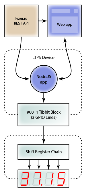
* These are Tibbo BASIC/C-programmable devices and their function depends on the loaded app.
We offer many ready-to-use apps, among them a serial-over-IP (SoI) app and Modbus Gateway app.
GPIO: Displaying currency exchange rate on 7-segment indicators

GPIO: Displaying currency exchange rate on 7-segment indicators

About the Application

This tutorial demonstrates the control of 7-segment LED indicators using a single Tibbit #00_1 and several shift register ICs (daisy-chained together).

  • 7-segment indicators (in fact, almost all modern indicators have eight segments) are cheap and reliable LED devices that can display decimal digits (and some characters). Every segment of such an indicator is controlled through a dedicated input, so driving all these inputs directly from the LPTS would require a lot of wires (32 lines for a 4-digit display). A more practical solution is to use shift registers.

  • In a nutshell, a shift register is a converter between serial and parallel interfaces. This tutorial uses 74HC595 — a very popular 8-bit shift register. This IC is controlled by three lines (clock, data, and latch) and has eight outputs — just enough to drive one indicator. Shift registers can be daisy-chained to increase the number of outputs. Driving such a chain still requires only three control lines.

  • This project uses four shift registers connected to four 7-segment indicators to display currency exchange rates provided by the fixer.io JSON API.

  • The app features a simple web interface for selecting the currency to be displayed.

What you need

Hardware

* Common anode devices would require a different connection scheme.

Onboard Software

  • Node.js V6.x.x (pre-installed during production)

External Services

The Hardware

  • Configure the LTPS as shown on the Tibbit layout diagram below.

  • Assemble the shift register chain and 7-segment indicators according to the wiring diagram below (wires connecting the 2nd, 3rd, and the 4th resistor blocks to their respective indicators are not shown).

Note: When the power is first applied the indicators may display a random pattern.

Node.js Application

  • The app uses the Request package to fetch data from fixer.io, the Express package to serve static files, and socket.io to facilitate a link between the onboard app and the web interface.
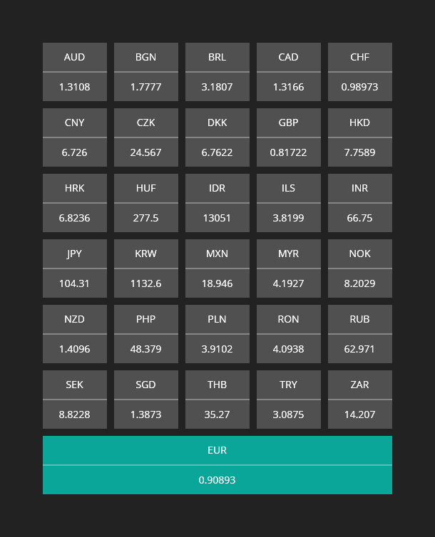
  • The application requests USD exchange rates for a number of currencies. Requests are made every ten minutes. Fixer.io updates the rates daily, around 4 pm CET.
  • By default, the USD/EUR rate will be displayed on the indicators.
  • The App's web server listens on port 3000.

Configuration and Installation

git clone https://github.com/tibbotech/gpio-indicators.git
cd gpio-indicators
npm install .
  • Launch:
node rates

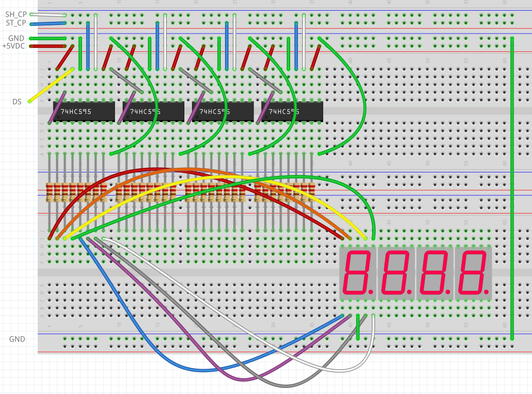
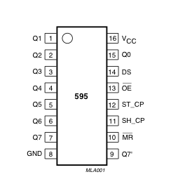
Controlling shift registers

The code that controls 7-segment indicators is found in /modules/indicate.js.

Comments in the code explain how it works:

const gpio = require("@tibbo-tps/gpio");

class indicator {
    constructor(socket, length){
        this.length = length;


        this.digits = {
            1: [0,1,0,0,1,0,0,0],
            2: [0,0,1,1,1,1,0,1],
            3: [0,1,1,0,1,1,0,1],
            4: [0,1,0,0,1,0,1,1],
            5: [0,1,1,0,0,1,1,1],
            6: [0,1,1,1,0,1,1,1],
            7: [0,1,0,0,1,1,0,0],
            8: [0,1,1,1,1,1,1,1],
            9: [0,1,1,0,1,1,1,1],
            0: [0,1,1,1,1,1,1,0],
            N: [0,0,0,0,0,0,0,1], // Dash symbol
            B: [0,0,0,0,0,0,0,0] // Blank symbol
        };

        // Sets up pins
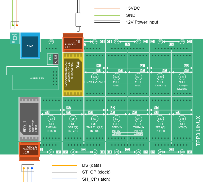
        this.dataPin = gpio.init(socket+"A");
        this.dataPin.setDirection("output");
        this.dataPin.setValue(0);

        this.clockPin = gpio.init(socket+"B");
        this.clockPin.setDirection("output");
        this.clockPin.setValue(0);

        this.latchPin = gpio.init(socket+"C");
        this.latchPin.setDirection("output");
        this.latchPin.setValue(0);
    }

    indicate(number){
        var inst = this;

        // Converts number to the array of signals to be sent
        const numberToSignals = function(number){
            var output =[];
            number
                .toString()
                .split("")
                .forEach(function(current, index, array){
                    if(current !== "."){
                        var symbol = inst.digits[current];
                        if (symbol === undefined){
                            symbol = Array.from(inst.digits["N"])
                        }else if(array[index+1] === "."){
                            symbol = Array.from(symbol);
                            symbol[0] = 1;
                        }
                        output.unshift(symbol);
                    }
                },[]);

            // crops number to the first "length" digits, if needed
            output = output.slice(-inst.length);

            // pads the number with spaces if it's shorter than 4 digits
            while (output.length < inst.length){
                output.push(inst.digits["B"])
            }

            return output.reduce(function(prev, current){
                return prev.concat(current)
            });
        };

        var signals = numberToSignals(number);

        // Sets ST_CP (latch) to LOW
        // This operation sets shift registers into "programming" mode.
        // When latch is LOW, shift register doesn't change output states,
        // but reads and "remembers" data from DS pin.
        inst.latchPin.setValue(0);

        signals.forEach(function(value){
            // sets value to be pushed into the register on DS pin
            inst.dataPin.setValue(value);

            // sets SH_CP (clock) to HIGH and then to LOW
            // on rising edge of the clock shift register reads state from DS pin, and prepares it for setting on Q0 output.
            // Each of the previously SET values will be shifted to the next pin.
            inst.clockPin.setValue(1);
            inst.clockPin.setValue(0);
        });

        // then all signals are sent, sets ST_CP (latch) to HIGH
        // If latch is HIGH, all the read values will be simultaneously set to the outputs.
        inst.latchPin.setValue(1);
    };
}

module.exports = indicator;

Web Interface

The web interface files are found in the -/static folder.

  • The web interface app requests data from fixer.io independently from the onboard app.
  • The Angular toolset is used to display the exchange rates table and provide interactivity.
  • The Socket.IO library is used to detect the board's status (the table will be hidden if the board is offline) and send the currency data to the board.
GPIO: Displaying currency exchange rate on 7-segment indicators