* These are Tibbo BASIC/C-programmable devices and their function depends on the loaded app.
We offer many ready-to-use apps, among them a serial-over-IP (SoI) app and Modbus Gateway app.
* These are Tibbo BASIC/C-programmable devices and their function depends on the loaded app.
We offer many ready-to-use apps, among them a serial-over-IP (SoI) app and Modbus Gateway app.
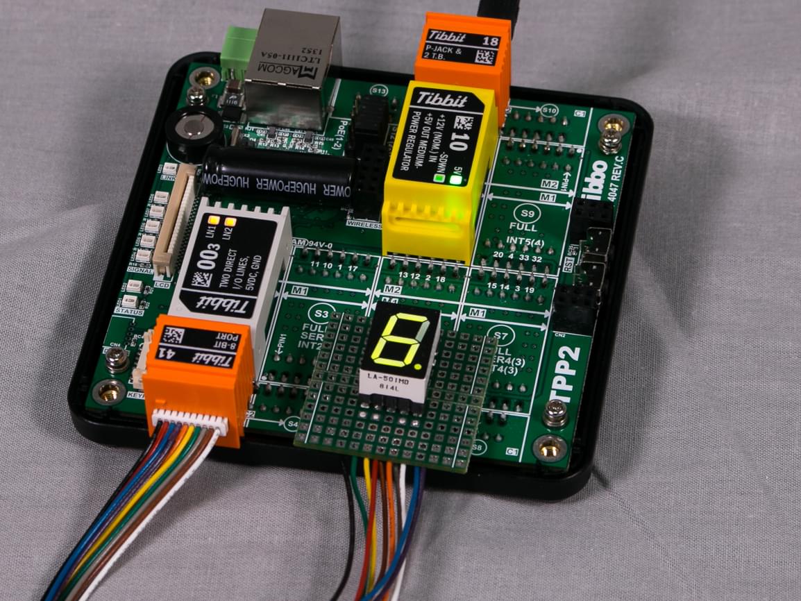
#57 (FPGA Tibbit) in smart LED controller configuration
Many projects in the collection output data using sys.debugprint method, which means that the projects are meant to be run in the debug mode.
Each Tibbit has its own personal mini project, with these exceptions:
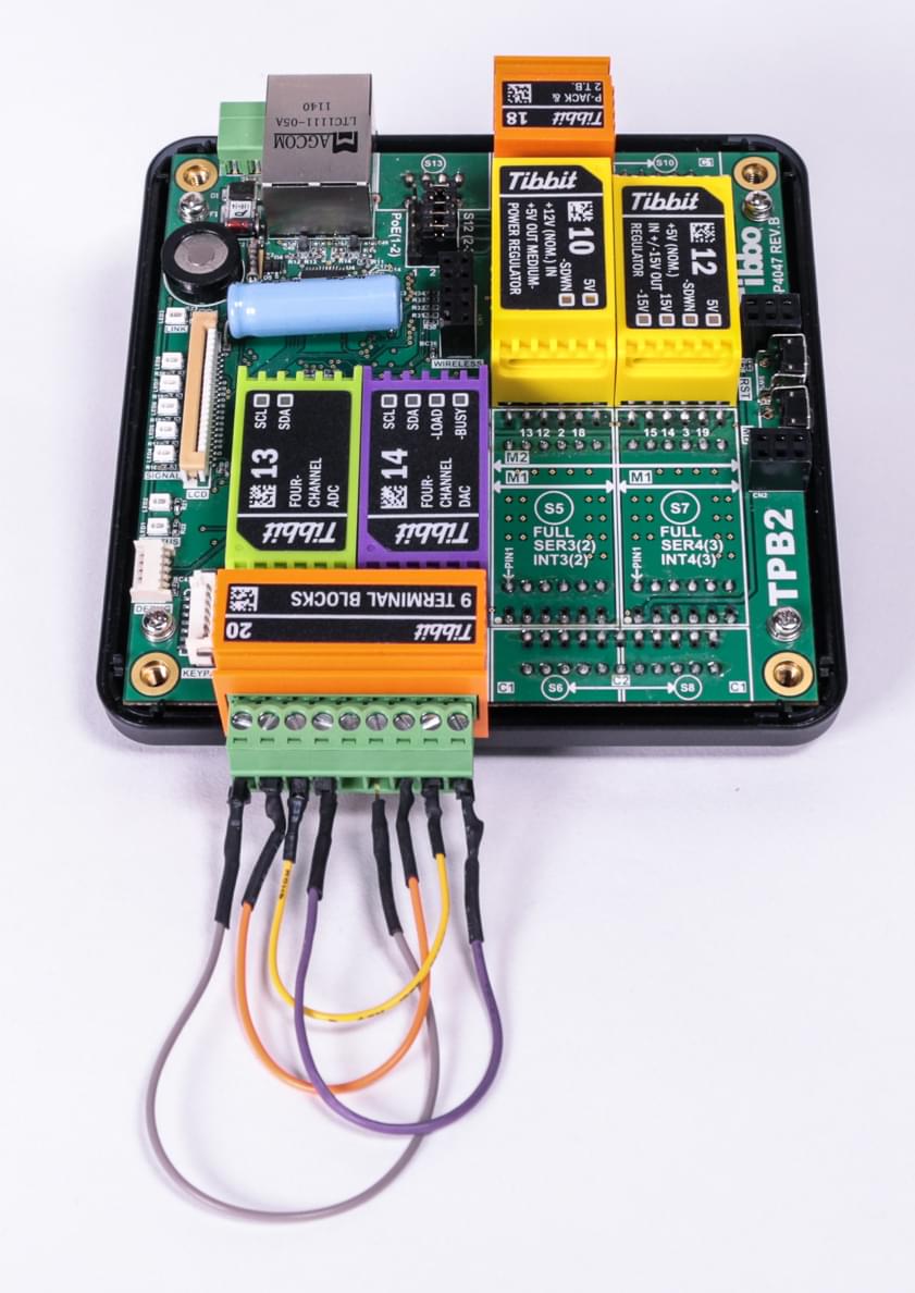
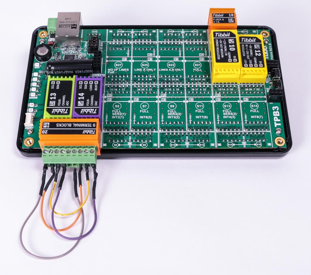
Tibbits #13 (ADC) and #14 (DAC) are "combined" into a single test app. There is an obvious convenience in this: ADCs can measure what DACs output.
Tibbits #16, #17, and #31 use the same test project. This is because they are based on the same PIC device 16F1824 running the same General Register Access (GRA) firmware (see below for details).
Both Tibbits are tested in the same project. The DAC outputs desired voltages and ADC acquires them.
You will need:
TPP2 or TPP3 board
One Tibbit #12 (+/-15V power supply)
One Tibbit #13 (4-channel ADC)
One Tibbit #14 (4-channel DAC)
One Tibbit #20 (9 terminal blocks)
Optionally, one Tibbit #9 or #10 (12V->5V regulator)
Optionally, one Tibbit #18 (power jack)
Last two Tibbits are necessary if you are going to power your rig from a 12V power adaptor. Alternatively you can supply regulated +5V power directly to the TPP.
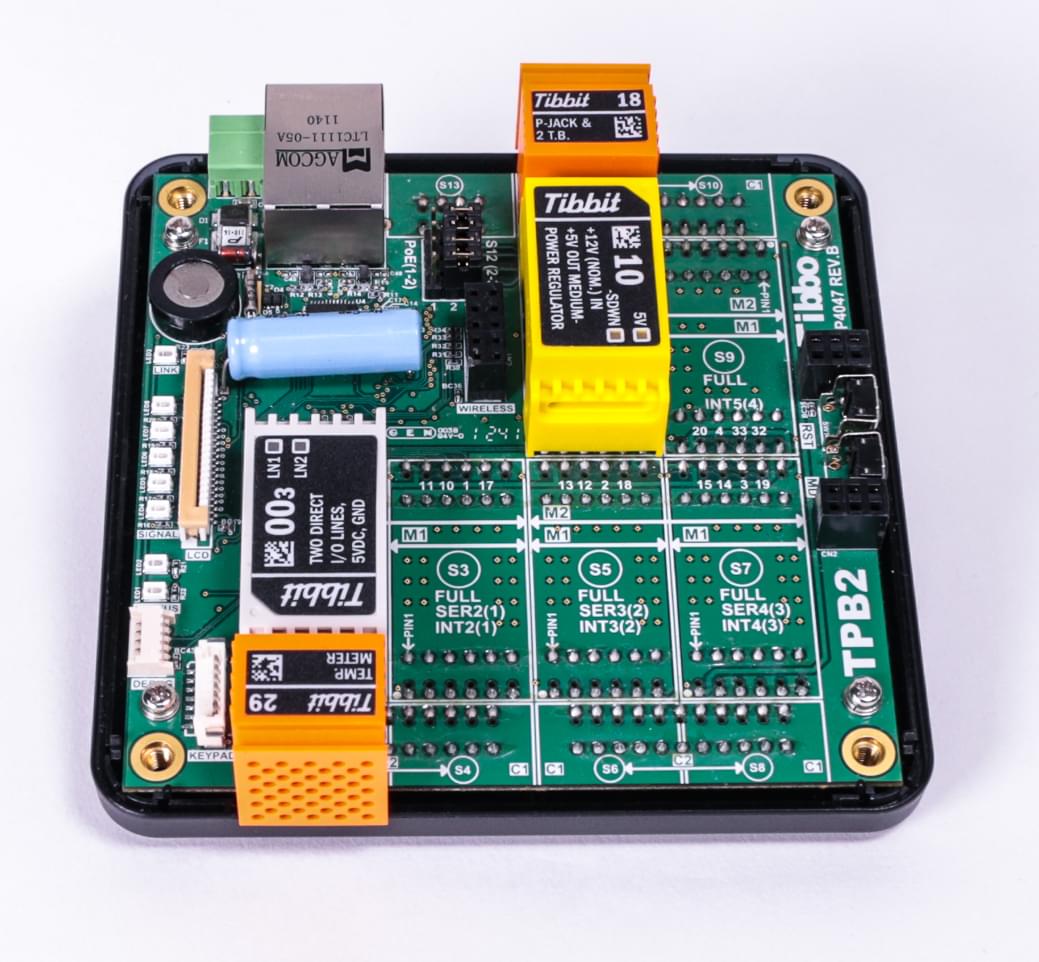
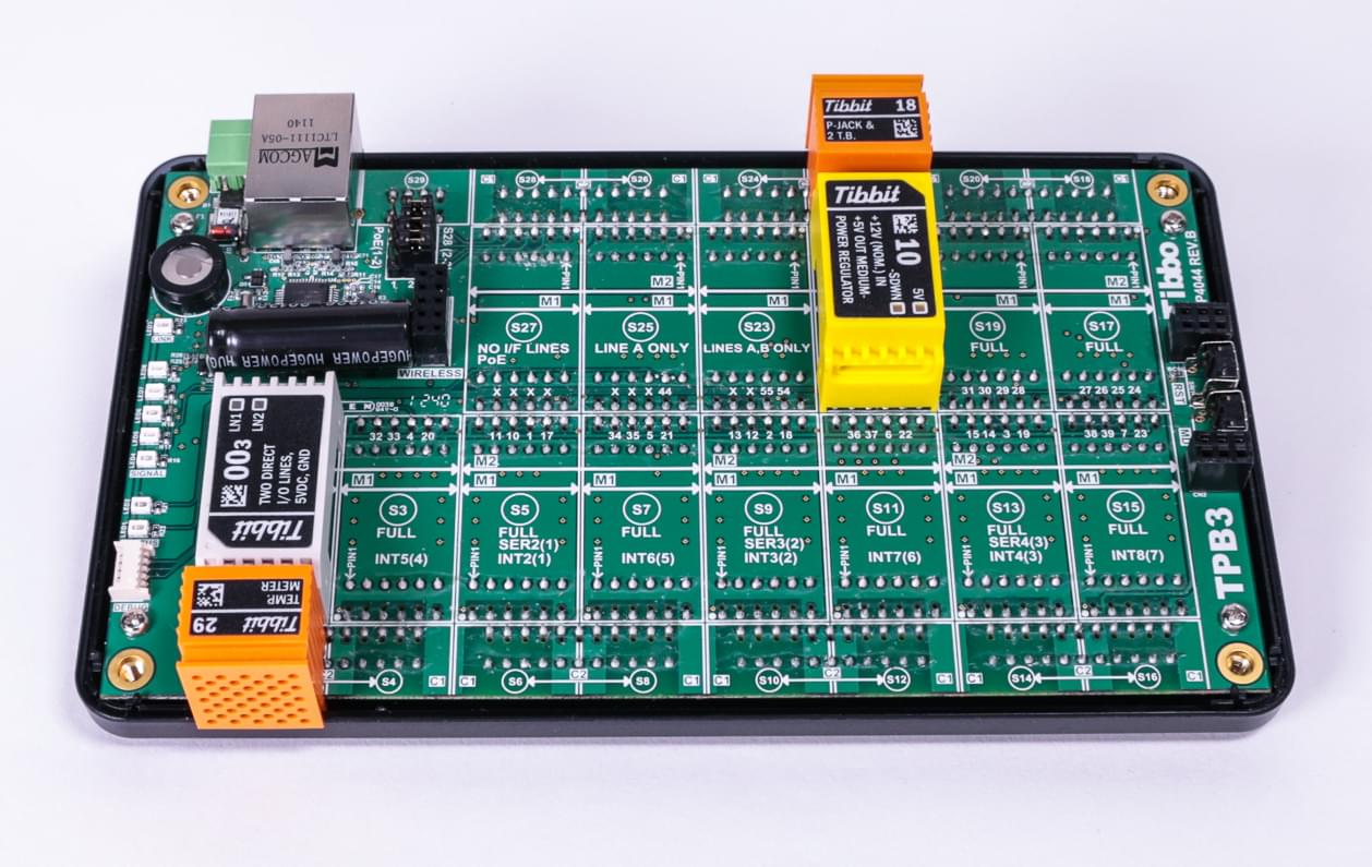
Pictures on the right illustrate the test arrangement. Notice the wires on the terminal block Tibbit. They interconnect ADC and DAC channels.
Both PWM Tibbits as well as the PIC coprocessor Tibbit are tested using the same project.
You will need:
TPP2 or TPP3 board
One Tibbit #16, #17, or #31
One Tibbit #00-3
One Tibbit #20 (9 terminal blocks)
Optionally, one Tibbit #9 or #10 (12V->5V regulator)
Optionally, one Tibbit #18 (power jack)
Last two Tibbits are necessary if you are going to power your rig from a 12V power adaptor. Alternatively you can supply regulated +5V power directly to the TPP. The test with RGB LED strip requires 12V power as well.
All three Tibbits are based on the PIC device 16F1824. This is a generic PIC microcontroller with a typically rich set of peripherals.
Tibbits #16 and #17 take advantage of PIC's PWM channels (three out of four are utilized).
Tibbit #31 has four I/O lines which can be used in the following ways:
Three lines have PWM capability;
All four lines can work as ADC inputs;
Two lines can act as TX and RX of the PIC's UART;
Each line can also function as a a regular input/output.
All three Tibbits ship with the GRA (general register access) firmware, which allows you to access internal PIC registers and memory through the I2C interface. The firmware implements a very simple communications protocol which essentially consists of two important commands — address read and address write. These two commands are used to write to and read from the internal PIC RAM and registers. This facilitates a simple and versatile access to all microcontroller resources.
Since the GRA firmware does not do anything intelligent and all the setup work is essentially scripted in Tibbo BASIC, it's possible to modify the behavior of PIC micro without making any changes to its firmware.
The GRA firmware of PIC-based Tibbits can be updated using the "update_pic_firmware" project, which is also included in this collection. The firmware is supplied with the source codes (see the "GRA" subfolder). You are free to use and modify the project in any way you like.
This Tibbo BASIC project has several test modes. The desired mode is selected in the following line of code in main.tbs:
test_item=TEST_IO '<<==================== SELECT DESIRED TEST CASE HERE
Tibbit #31 (PIC coprocessor) supports all test modes. PWM Tibbits #16 and #17 should only be tested using PWM tests.
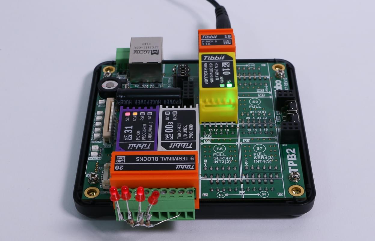
TEST_IO (Tibbit #31 only)
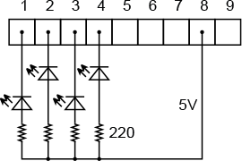
For this test we recommend using four small LEDs. Plug Tibbits as shown in the photo on the right. Tibbit #0-3 is there to supply 5V power to the LEDs. Connect four LEDs as shown on the following diagram:
This test implements the binary counter. The leftmost LED blinks at the fastest rate (it represents the least significant bit of the counter). The rightmost LED blinks at the slowest rate (it represents the most significant bit of the counter).
TEST_PWM_1 and TEST_PWM_2 on Tibbits #16 and #31
Same LED circuit can be used for testing, although the rightmost LED won't work as there are only three PWM channels.
TEST_PWM_1 demonstrates how each PWM channel can run at its own independently set frequency and duty cycle. You will need to use a scope to see the difference.
TEST_PWM_2 is more visual. All three PWMs are set to the same frequency, and have their duty cycles gradually change. You will see how the light emitted by LEDs changes in brightness.
TEST_PWM_2 on Tibbits #17
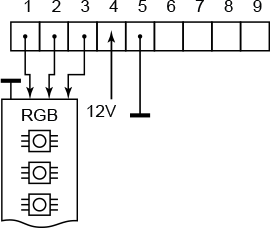
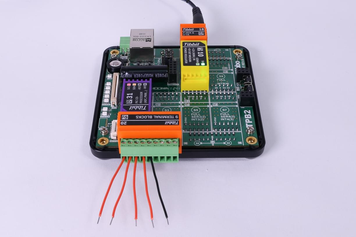
Tibbit #17 was designed specifically for controlling RGB LED strips. Connect a strip as shown on the diagram below and a photo on the right.
Note that 12V power for the LED strip is fed into the Tibbit #17. In our test arrangement we get this power from the wall adaptor. This is achieved by tapping into the power lines of Tibbit #18 (it has 2 terminal blocks and a power jack connected in parallel).
The current consumed by LED strips is very high and can reach several amps. Be sure to use an appropriate power source for this test.
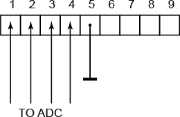
ADC tests (Tibbit #31 only)
Use any suitable voltage source (i.e. a lab power supply) to apply varying voltages to I/O lines 1-4. Measurement results will be printed using sys.debugprint.
Three tests only differ in the reference voltage used. In any case, be careful to only apply voltages in the 0-5V range. Exceeding 5V may permanently damage the PIC micro.
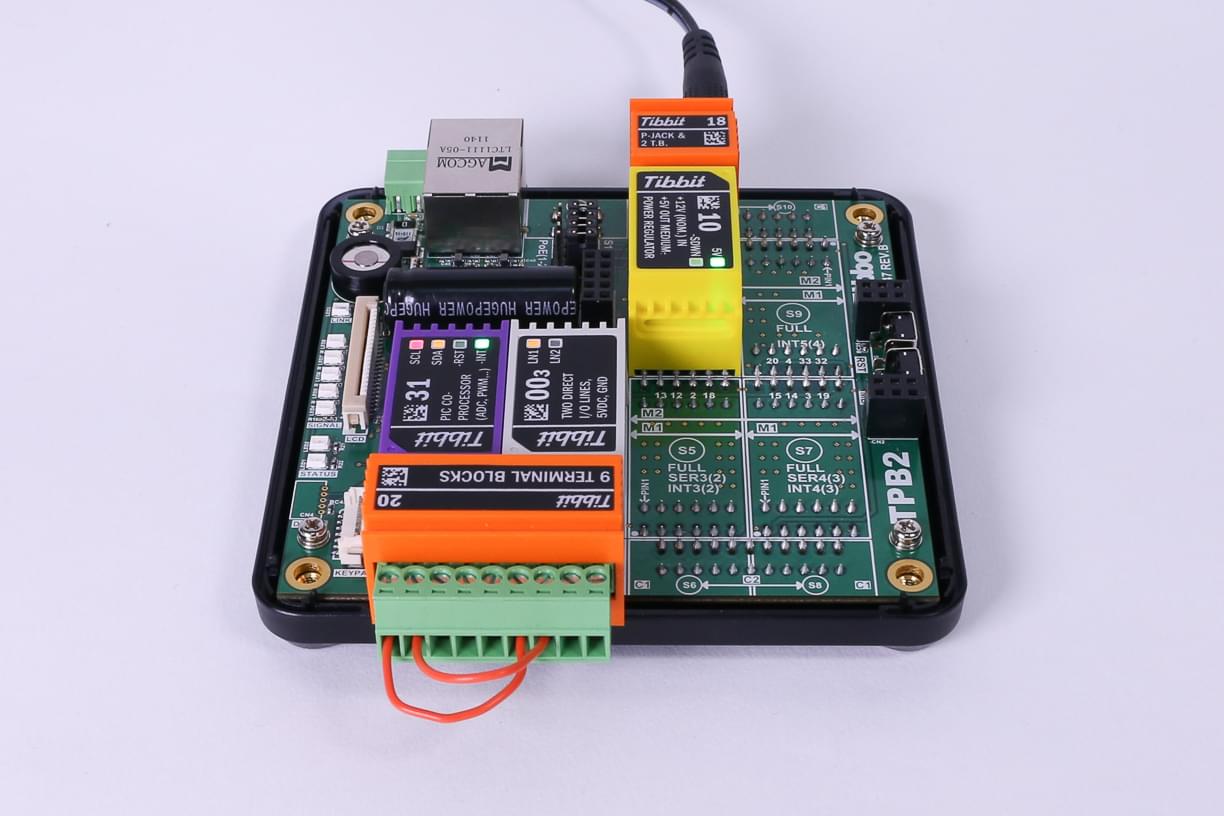
TEST_UART_1 (Tibbit #31 only)
This is a loopback test in which the data is juggled between the RX and TX lines of the PIC micro. Interconnect I/O lines 1 and 2 and run the test in debug mode (so you could see debug printing).
TEST_UART_2 (Tibbit #31 only)
This is a more sophisticated test. The data is bounced between the PIC's UART and the serial port SER2(1) of your TPP board. One more Tibbit (#0-3) is needed for this.
On TPP2 board, interconnect terminal blocks 1-6 and 2-7. Run the test in debug mode (so you could see debug printing). The test arrangement will be different on TPP3 where SER2(1) is father away.
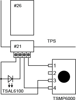
An IR remote from your aircon, TV, or some other appliance
Vishay TSAL6100 IR LED (or another IR LED)
Vishay TSMP6000 IR receiver (or another suitable receiver)
TPP2 or TPP3 board
One Tibbit #26 (IR command processor)
One Tibbit #21 (4 terminal blocks)
Optionally, one Tibbit #9 or #10 (12V->5V regulator)
Optionally, one Tibbit #18 (power jack)
The last two Tibbits are necessary if you are going to power your rig from a 12V power adaptor.
Alternatively, you can supply regulated +5V power directly to the TPP.
Plug Tibbit #26 into the socket S1, Tibbit #21 into S2. Connect the IR LED and receiver to the terminal blocks of Tibbit #21 as shown in the diagram.
Open "test_tibbit_26_(IR proc)" Tibbo BASIC project and configure global variables (this is done in the on_sys_init() event handler).
For example, if you are using Vishay IR LED and receiver recommended above, configure these three global variables as follows:
inverted_output = NO
inverted_input = NO
carrier_present = YES
Run the project. Once the system is ready, the green status LED will be turned on. You can now teach an IR code.
For this, press and hold the MD button. Keep holding the button down until the green status LED starts blinking.
Without releasing the button, point the IR remote toward the IR receiver and push a button on the remote that you want the TPS to learn.
Release the button. If the signal acquisition was successful, the green status LED will stop blinking and stay ON.
If learning failed, red status LED will be blinking.
Once the IR code has been learned, press and release the MD button to emit the same code from the IR LED connected to your TPS.
Optionally, one Tibbit #9 or #10 (12V->5V regulator)
Optionally, one Tibbit #18 (power jack)
Last two Tibbits are necessary if you are going to power your rig from a 12V power adaptor. Alternatively you can supply regulated +5V power directly to the TPP.
Pictures on the right illustrate the test arrangement. All sensor Tibbits are plugged into the same socket C1.
Optionally, one Tibbit #9 or #10 (12V->5V regulator)
Optionally, one Tibbit #18 (power jack)
Last two Tibbits are necessary if you are going to power your rig from a 12V power adaptor. Alternatively you can supply regulated +5V power directly to the TPP.
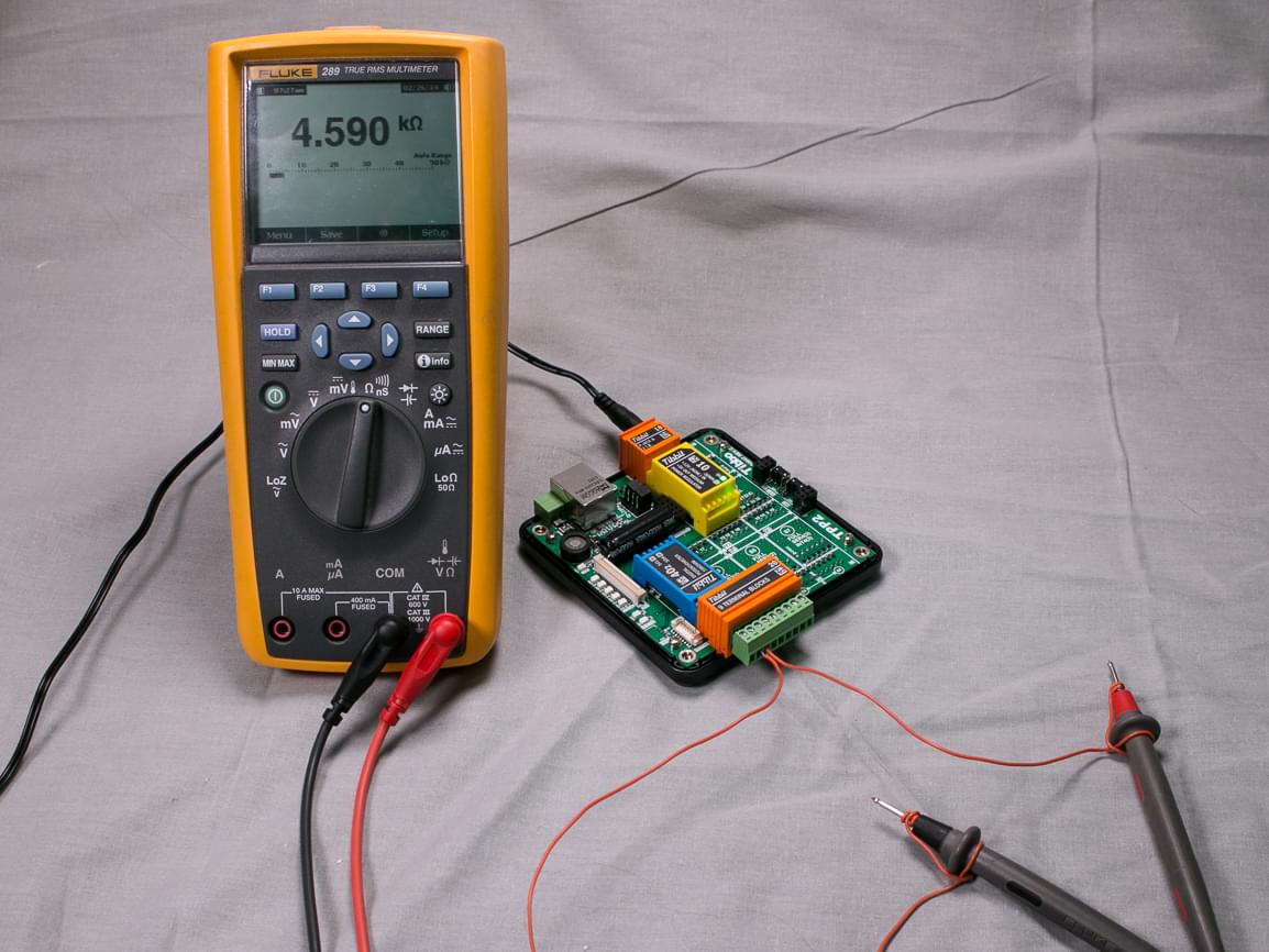
This Tibbit is based on the MCP4561 digital POT IC from Microchip. Tibbo supplies the Tibbit in 5KOhm, 10KOhm, 50KOhm, and 100KOhm versions.
The test application is meant to be executed in debug mode. We've placed breakpoints on lines where you need to stop and observe the result.
The application tests the digital POT in three steps:
First, you will break after executing tbt40_set(256,NO). This sets the POT to the maximum value it can produce. You will observe this value between pins 3 and 4 of Tibbit #40 (terminal blocks 2 and 3 on Tibbit #20).
The actual impedance value will differ from the nominal one. For example, you may get 4.6KOhm out of the 5KOhm Tibbit. The variation of +/-10% is to be expected.
Once you know the actual range of your Tibbit, exit the debug mode and set the FULL_SCALE constant to this value (for example, FULL_SCALE=4600). Now run the program again. Press F5 until you stop past the tbt40_set_ohm(FULL_SCALE/2,FULL_SCALE,YES) line. Executing it will set the POT to 1/2 of its max impedance. Since the FULL_SCALE constant is already adjusted to reflect the actual range of the IC you are testing the resulting impedance will be quite accurate.
Stopping at the third breakpoint will set the impedance to 1/3 of the max value.
Project name: "test_tibbit_41_(8-bit port extender)".
You will need:
TPP2 or TPP3 board
One Tibbit #41, it is supplied with a 200mm cable
One Tibbit #00-3;
Optionally, one Tibbit #9 or #10 (12V->5V regulator)
Optionally, one Tibbit #18 (power jack)
Last two Tibbits are necessary if you are going to power your rig from a 12V power adaptor. Alternatively you can supply regulated +5V power directly to the TPP.
Tibbit #41 is based on the MCP23008 8-bit port extender IC from Microchip.
This Tibbo BASIC project has several test modes. The desired mode is selected in the following line of code in main.tbs:
test_item=TEST_BYTE_IN '<<====================== SELECT DESIRED TEST CASE HERE
The first test mode — TEST_BIT_OUT — implements an 8-bit counter. The code uses individual IO line manipulation to read and write the state of IO lines. Use the scope to observe that line GP0 is constantly switching between LOW and HIGH states. Line GP1 switches at 1/2 of GP0 frequency. Line GP2 switches at 1/2 of GP1 frequency, and so on.
The second test mode — TEST_BYTE_OUT — implements the same counter but relies on the port-wide (byte) reads and writes.
The TEST_BYTE_IN mode implements line state tracking. The current state of eight I/O lines is printed using sys.debugprint. Obviously, you will need to run the application in the debug mode to be able to see this debug output.
Since this test enables pull-up resistors on all I/O lines each line will read as 1 (HIGH) unless you ground it.
Testing Tibbit #42 (RTC and NVRAM with backup battery and interrupt output)
Project name: "test_tibbit_42_(RTC)".
You will need:
TPP2 or TPP3 board
One Tibbit #42
Optionally, one Tibbit #9 or #10 (12V->5V regulator)
Optionally, one Tibbit #18 (power jack)
Last two Tibbits are necessary if you are going to power your rig from a 12V power adaptor. Alternatively you can supply regulated +5V power directly to the TPP.
Tibbit #42 is based on the DS3234 high-precision RTC from Maxim Integrated.
This Tibbo BASIC project has several test modes. The desired mode is selected in the following line of code in main.tbs:
test_item=test_item=TEST_NVRAM '<<====================== SELECT DESIRED TEST CASE HERE
Tests are meant to be run in the debug mode as most test cases rely on sys.debugprint.
TEST_RTC_SET mode sets the RTC to the specified date and time. We understand it looks a bit strange that you need to manually set the clock. Obviously, there are ways to obtain the current data/time from the internet. Our rationale is that this is a simple test project, not a complete application. We didn't want to clutter the app with code which is not directly related to testing the RTC Tibbit.
The next test mode — TEST_RTC_GET — will repeatedly print the current date and time using the sys.debugprint method.
TEST_ALARM_EVERY_SEC will demonstrate the RTC's ability to trigger periodic alarms. In this test the alarm will be programmed to trigger every second. The code will wait until the -INT/MISO line is set LOW, thus indicating that the alarm has happened. The program will then print the current date/time and start waiting for the next alarm.
TEST_ALARM_EVERY_MIN is like the previous test, but the alarm will trigger every minute.
TEST_ALARM_AT_PRESET_DATE_TIME demonstrates yet another alarm feature of the DS3234 — the ability to trigger alarm once at preset date and time. This test will read the current date/time, then set the date/time alarm to trigger one minute later.
TEST_TEMP will repeatedly print the current temperature measured by the IC.
Finally, TEST_NVRAM will perform a write-and-read-back test of the IC's non-volatile RAM.
Testing Tibbit #57 (FPGA Tibbit) in smart LED controller configuration
Rolling Color
Shifting Color
Project name: "test_tibbit_57_(RGBW)".
You will need:
TPP2 or TPP3 board
One Tibbit #57
One Tibbit #20
Optionally, one Tibbit #00-3 (if you are going to power your smart LEDs from your TPS system)
Optionally, one Tibbit #10 (12V->5V regulator)
Optionally, one Tibbit #18 (power jack)
Several SK6812RGBW LEDs (or a board, or LED strip containing these LEDs).
Last two Tibbits are necessary if you are going to power your rig from a 12V power adaptor. Alternatively you can supply regulated +5V power directly to the TPP.
Tibbit #57 is based on the ICE5LP2K-SWG36ITR50 FPGA from Lattice Semiconductor.
This FPGA is suitable for a large number of projects. One such project is the smart LED controller.
In the smart LED configuration, Tibbit #57 can control a string of daisy-chained SK6812RGBW LEDs.
SK6812RGBW devices carry a small IC driving four onboard light emitters with red, green, blue, and white colors.
Each of the color sources can be set to one of the 256 levels of brightness, meaning that four bytes of data are needed per LED.
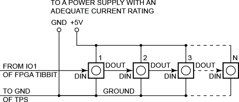
Smart LEDs are controlled via a special 1-wire protocol. Each LED has a DIN (data in) and DOUT (data out) pins.
The DIN pin of the first LED in the chain is connected to the IO1 line of the FPGA Tibbit.
The DOUT of the first LED is connected to the DIN of the second LED, the DOUT of the second LED — to the DIN of the third LED, and so on.
Depending on the number of LEDs you are connecting, you may be able to power them from your TPS, or you may need to use an external +5V power supply.
R, G, and B emitters of each LED consume up to 9mA each, the white emitter consumes up to 18 mA.
Count the available current and choose the right power source!
Before you run the application, set the actual number of LEDs you have connected in the "Const NUM_LEDS=" line.
The test application has three modes — PATTERN_1, PATTERN_2, PATTERN_3. Select the mode in the "Dim pattern_mode as pattern_modes=" line.
PATTERN_1: All LEDs set to the same color, the color will gradually change from R to G, from G to B, and from B to R.
PATTERN_2: A moving pattern of RGB colors.
PATTERN_3: White LEDs all set to the same brightness, and the brightness gradually changes between minimum and maximum.
The longer your LED chain is, the slower the "animation" runs.
If you have a small number of LEDs connected (10-20), then you may discover that everything changes too fast.
In that case, increase the delay specified by the "Const LED_OUTPUT_DELAY=" line.