* These are Tibbo BASIC/C-programmable devices and their function depends on the loaded app.
We offer many ready-to-use apps, among them a serial-over-IP (SoI) app and Modbus Gateway app.
* These are Tibbo BASIC/C-programmable devices and their function depends on the loaded app.
We offer many ready-to-use apps, among them a serial-over-IP (SoI) app and Modbus Gateway app.
Both PWM Tibbits as well as the PIC coprocessor Tibbit are tested using the same project.
You will need:
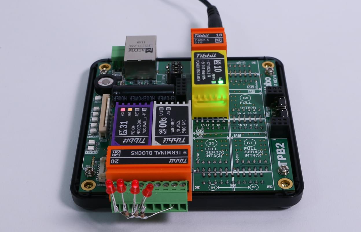
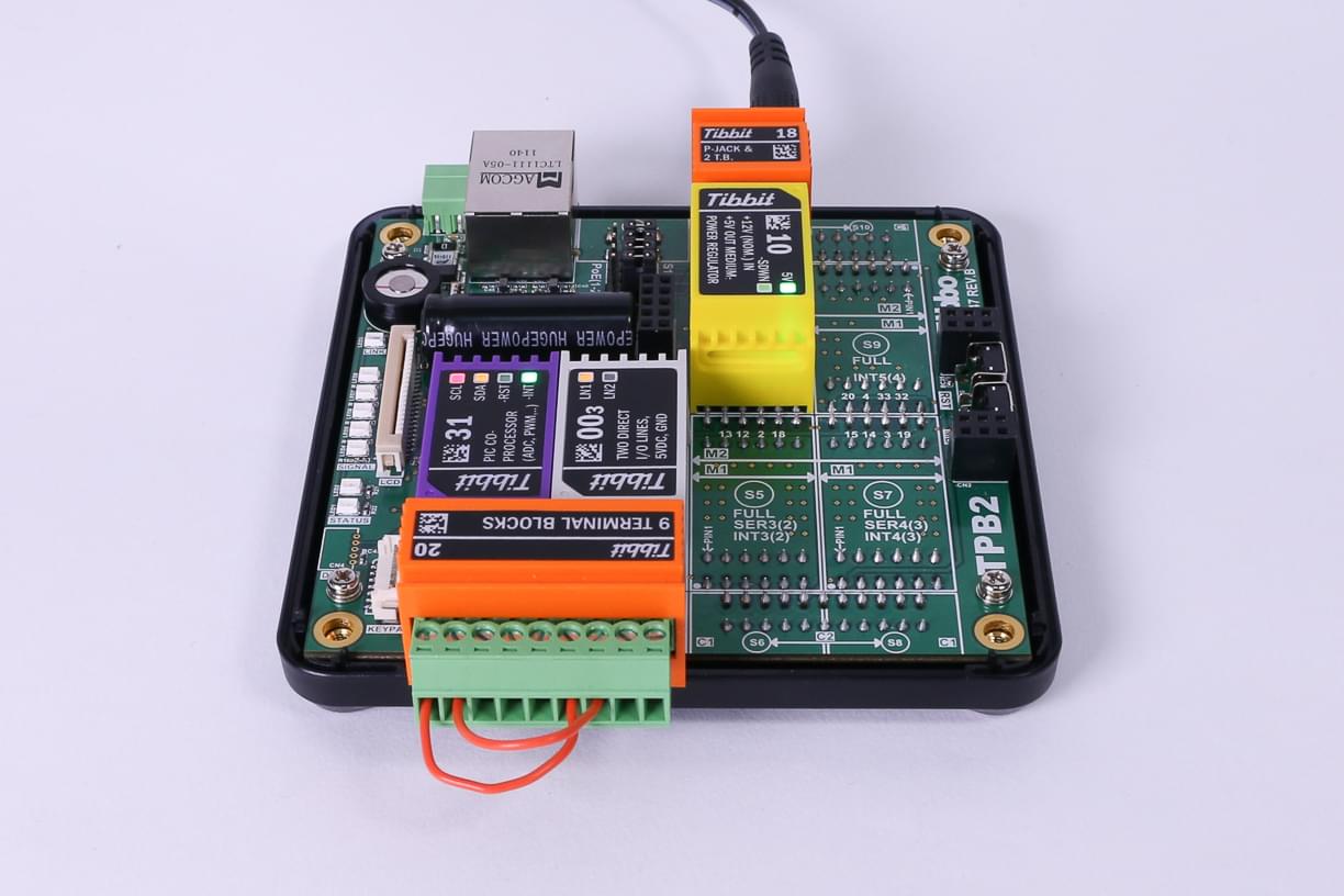
TPP2, TPP2(G2), TPP3, or TPP3(G2) board
One Tibbit #16, #17, or #31
One Tibbit #00-3
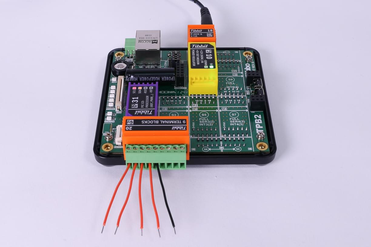
One Tibbit #20 (9 terminal blocks)
Optionally, one Tibbit #9 or #10 (12V->5V regulator)
Optionally, one Tibbit #18 (power jack)
The last two Tibbits are necessary if you are going to power your rig from a 12V power adaptor. Alternatively you can supply regulated +5V power directly to the TPP. The test with an RGB LED strip requires 12V power as well.
All three Tibbits are based on the PIC16F1824 device. This is a generic PIC microcontroller with a typically rich set of peripherals.
Tibbits #16 and #17 take advantage of PIC's PWM channels (three out of four are utilized).
Tibbit #31 has four I/O lines that can be used in the following ways:
Three lines have PWM capability
All four lines can work as ADC inputs
Two lines can act as TX and RX of the PIC's UART
Each line can also function as a a regular input/output
All three Tibbits ship with the GRA (general register access) firmware, which allows you to access internal PIC registers and memory through the I2C interface. The firmware implements a very simple communications protocol that essentially implement two important commands — address read and address write. These two commands are used to write to and read from the internal PIC RAM and registers. This facilitates a simple and versatile access to all microcontroller resources.
Since the GRA firmware does not do anything intelligent and all the setup work is scripted in Tibbo BASIC, it's possible to modify the behavior of PIC micro without making any changes to its firmware.
The GRA firmware of PIC-based Tibbits can be updated using the "update_pic_firmware" project, which is also included in the .zip file.
This Tibbo BASIC project has several test modes. The desired mode is selected in the following line of code in main.tbs:
test_item=TEST_IO '<<==================== SELECT DESIRED TEST CASE HERE
Tibbit #31 (PIC coprocessor) supports all test modes. PWM Tibbits #16 and #17 should only be tested using PWM tests.
TEST_IO (Tibbit #31 only)
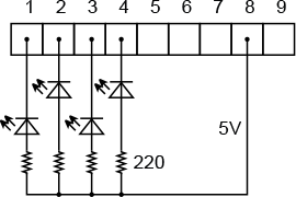
For this test we recommend using four small LEDs. Insert Tibbits as shown on the right photo. Tibbit #0-3 is there to supply 5V power to the LEDs. Connect the LEDs as shown on the diagram:
The test implements a binary counter. The leftmost LED blinks at the fastest rate (it represents the least significant bit of the counter). The rightmost LED blinks at the slowest rate (it represents the most significant bit of the counter).
TEST_PWM_1 and TEST_PWM_2 on Tibbits #16 and #31
The same LED circuit can be used for testing, although the rightmost LED won't work as there are only three PWM channels.
TEST_PWM_1 demonstrates how each PWM channel can run at its own independently set frequency and duty cycle. You will need to use a scope to see the frequency difference.
TEST_PWM_2 is more visual. All three PWMs are set to the same frequency, and have their duty cycles gradually change. You will see how the light emitted by LEDs changes in brightness.
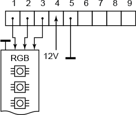
TEST_PWM_2 on Tibbits #17
Tibbit #17 was designed specifically for controlling RGB LED strips. Connect a strip as shown on the diagram below.
Note that 12V power for the LED strip is fed into the Tibbit #17. In our test arrangement we supplied this power from the same wall adaptor that powered the TPS itself. This was achieved by tapping into the power lines of Tibbit #18 (it has 2 terminal blocks and a power jack connected in parallel). You can see how we did this in the video below.
The current consumed by LED strips is very high and can reach several amps. Be sure to use an appropriate power source for this test.
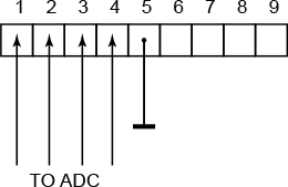
ADC tests (Tibbit #31 only)
Use any suitable voltage source (i.e. a lab power supply) to apply varying voltages to I/O lines 1-4. Measurement results will be printed using sys.debugprint. Therefore, you must run this test in debug mode.
Three tests only differ in the reference voltage used. In any case, be careful to only apply voltages in the 0-5V range. Exceeding 5V may permanently damage the PIC micro.
TEST_UART_1 (Tibbit #31 only)
This is a loopback test in which the data is juggled between the RX and TX lines of the PIC micro. Interconnect I/O lines 1 and 2 and run the test in debug mode (so you could see debug printing).
TEST_UART_2 (Tibbit #31 only)
This is a more sophisticated test. The data is bounced between the PIC's UART and the serial port SER2(1) of your TPP board. One more Tibbit (#0-3) is needed for this. And why do you need to use Tibbit #0-3 and not an RS232 Tibbit, such as #01? Because the PIC copro Tibbit works with CMOS-level, not RS232-level signals.
On the TPP2 board, interconnect terminal blocks 1-6 and 2-7. Run the test in debug mode (so you could see debug printing). The test arrangement will be different on TPP3 where SER2(1) is father away.